-
 ΔικτυακάΣΥΝΕΧΕΙΑ ΝΕΕΣ ΑΦΙΞΕΙΣ
Routers, switches, Οπτική Ίνα, Access Points -
 Ηλεκτρονικά
MCU, Arduino, Raspberry, Noctua, Αξεσουάρ -
 Ajax Συναγερμός
Ασύρματο Σύστημα Baseline -
 3D Printers/CNC/Laser
Filaments, DIY, Accessories -
 ΤηλεόρασηTeleves & Edision
Κεραιοσυστήματα, Modulators, Καλώδια -
 Προϊόντα WURTHΨΑΞΕ ΕΔΩ...
Ποικιλία που μεγαλώνει απο μέρα σε μέρα -
 Εργαλεία TOTALΓΚΑΜΑ ΠΟΥ ΜΕΓΑΛΩΝΕΙ
Εργαλεία για διάφορες δουλειές -
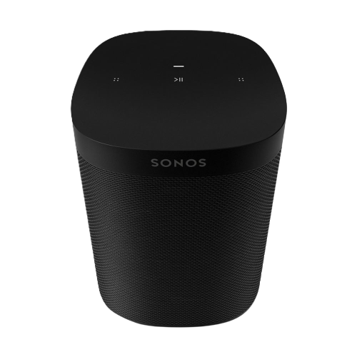 Audio & VideoLike Sonos
Είδη Ήχου / Βίντεο & Περιφερειακά -
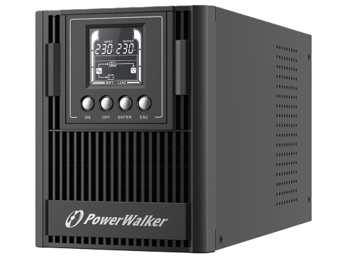 UPS & Καλώδια
Βρείτε Powerwalker και καλώδια -
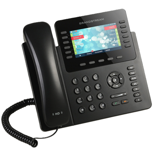 IP PBX Equipment
VoIP, Appliances, Gateways -
 Νέα προϊόνταΓΙΑ ΝΑ ΤΣΕΚΑΡΕΙΣ...
Γνωρίστε τα νέα προϊόντα μας! -
 InstatechPRO OpenBoxesSpecial Prices
Προϊόντα απο το κανάλι μας στο Youtube!
-
Δικτυακά
ΣΥΝΕΧΕΙΑ ΝΕΕΣ ΑΦΙΞΕΙΣ
Routers, switches, Οπτική Ίνα, Access Points- Ubiquiti Networks
-
MikroTik
- hEX Series
- hAP Series
- L009 Series
- RB4xxx & 5xxx
- CSS Series
- CRS Series
- CCR Series
- Chateau Series
- RB1100 Series
- RBcAP / mAP
- 60GHz Series
- PowerLine
- Groove & Metal
- LtAP Series
- IoT Series
- mANT & mANTBox
- MikroTik Accessories
- BaseBox, Netbox, Netmetal
- LoRA
- SXT Series
- wAP Series
- OmniTik Series
- LHG & ATL Series
- QRT & Sextant
- MikroTik Routerboards
- CWDM (MUX/DEMUX)
- Interfaces
- Teltonika
- TP-Link
- GL-iNet
- Peplink
- PoE Adapters
- Deva
- Οπτικές ίνες
- Δομημένη καλωδίωση
- SFP/SFP+/SFP28 Modules & DAC
- Καλώδια δικτύου
- Grandstream Networking
- Media Converters
- Noyafa Instruments
- Wavertech
- QuWIRELESS
- Κεραίες Συστημάτων
- Synology
- NetSys
-
Ηλεκτρονικά
MCU, Arduino, Raspberry, Noctua, Αξεσουάρ- Arduino
- Raspberry Pi
- Orange Pi
- Noctua
- MCU & Modules
- Εξοπλισμός & εργαλεία
- Μπαταρίες
- Kits
- Power supply
- LED Strips & Cobs
- Κουτιά κατασκευών / Din rail
- Alarm & CCTV
- IOT smart systems
- Fans / Cooling
- Phone Adapters
- SD / MicroSD Cards
- DC Motors
- Linear Actuators
- USB Cables
-
Ajax Συναγερμός
Ασύρματο Σύστημα Baseline -
3D Printers/CNC/Laser
Filaments, DIY, Accessories -
Τηλεόραση
Televes & Edision
Κεραιοσυστήματα, Modulators, Καλώδια -
Προϊόντα WURTH
ΨΑΞΕ ΕΔΩ...
Ποικιλία που μεγαλώνει απο μέρα σε μέρα -
Εργαλεία TOTAL
ΓΚΑΜΑ ΠΟΥ ΜΕΓΑΛΩΝΕΙ
Εργαλεία για διάφορες δουλειές -
Audio & Video
Like Sonos
Είδη Ήχου / Βίντεο & Περιφερειακά -
UPS & Καλώδια
Βρείτε Powerwalker και καλώδια -
IP PBX Equipment
VoIP, Appliances, Gateways -
Νέα προϊόντα
ΓΙΑ ΝΑ ΤΣΕΚΑΡΕΙΣ...
Γνωρίστε τα νέα προϊόντα μας! -
InstatechPRO OpenBoxes
Special Prices
Προϊόντα απο το κανάλι μας στο Youtube!
Τεχνικές ερωτήσεις για ηλεκτρονικά εξαρτήματα ΜΟΝΟ τηλεφωνικά καθημερινές 9:00 - 17:00 εκτός Σαββάτου
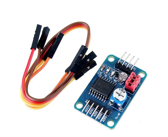
PCF8591 AD/DA Converter - Analog to Digital Module
Κωδικός e-Wireless: 1116.478
Αποστέλλουμε παραγγελίες σε όλη την Ελλάδα με ΕΛΤΑ Courier και ACS
Για να σας λύνονται όλες οι τεχνικές απορίες
Αρκεί το προϊόν να μην έχει ανοιχτεί και να μην έχουν προκληθεί φθορές στην συσκευασία του
E-WIRELESS
Αναλυτική Παρουσίαση
PCF8591 key performance indicators:
- Single-Supply Operation
- PCF8591 operating voltage range of 2.5V to 6V
- Low standby current
- through the I2C bus serial input / output
- PCF8591 by 3 hardware address pins addressing
- Sampling rate PCF8591 I2C bus rate decided
- 4 analog inputs programmable as single-ended or differential inputs
- Automatic incremental channel selection
- PCF8591 analog voltage range from VSS to VDD
- PCF8591 built-in track and hold circuit
- 8-bit successive approximation A / D converter
- through an analog output DAC gain
Description:
1. A module chip using PCF89512. module supports external voltage input capture (input voltage range 0-5v)3. Three modules integrated photoresistor acquisition environment through the AD intensity accurate numerical4. modules integrated thermistor, can capture the precise value of the ambient temperature through the AD5. The five-module integrated 1 channel 0-5V voltage input acquisition (blue potentiometer to adjust the input voltage)6. modules with power indicator light (on the module after power indicator lights)7. modules with the DA output indicator light board DA output indicator module DA output interface voltage reaches a certain value, the voltage the greater the light brightness is more obvious;8. module PCB size: 3.6cm * 2.3cm9. standard double-sided, plate thickness 1.6mm, the layout is nice, surrounded by the through-hole, aperture: 3mm, convenient fixed
The module interface:
The module's left and right, respectively, the external expansion of 2-way pin interface, respectively, as follows:Output interface of the left the AOUT chip DAThe AINO chip analog input interface.AIN1 chip analog input interfaceAIN2 chip analog input interfaceAIN3 chip analog input interfaceThe right side of the SCL IIC clock interface to access the microcontroller IO portThe SDA IIC digital interface connected microcontroller IO portGND module to an externalVCC power supply interface external 3.3v-5v
Module red jumper instructions for useModule three red short circuit cap, respectively, the role are as follows:P4 connected to the P4 jumper, select thermistor access circuitP5 connected to P5 jumper to select the photoresistor access circuitP6 connected to the P6 jumper, to select 0-5V adjustable voltage access circuit
e-Wireless
Τεχνικές Προδιαγραφές
- QoS
- Νομοθεσία
Για την καλύτερη απόδοση και σωστή λειτουργία όλων των συσκευών πρέπει σε κάθε εγκατάσταση να χρησιμοποιούνται τα εγκεκριμένα υλικά
Προσοχή!
Βάσει της ισχύουσας Ελληνικής Νομοθεσίας, του Ε.Κ.Κ.Ζ.Σ. (ΦΕΚ 47/2002, ΠΔ44 Άρθρο 1, Παρ 2), το προϊόν αυτό είναι εγκεκριμένο με τον τύπο CE (!).
H νόμιμη χρήση των προϊόντων που χρησιμοποιούν τη ζώνη συχνοτήτων 2400 – 2483,5 MHz, πρέπει να έχουν μέγιστη ισχύ εκπομπής τα 100 mW e.i.r.p. Στην ισχύ αυτή συνυπολογίζεται η ισχύς εξόδου του πομπού και η προσθήκη ισχύος της κεραίας.
Αρμόδια για την εποπτεία του φάσματος στην Ελληνική Επικράτεια είναι η E.E.T.T.
- Λεωφ. Βουλιαγμένης 571, Αργυρούπολη Αττικής
Χάρτης / Φόρμα Επικοινωνίας - info@e-wireless.gr
- Fax: +30 2109922401
© 2004 - 2025 e-Wireless.gr. Production by interTEN

Η ιστοσελίδα χρησιμοποιεί cookies για την ευκολία της περιήγησης, την εξατομίκευση περιεχομένου και διαφημίσεων και την ανάλυση της επισκεψιμότητάς μας. Δείτε τους ανανεωμένους όρους χρήσης για την προστασία δεδομένων και τα cookies.
Τα παρακάτω cookies μας βοηθούν να βελτιώνουμε την εμπειρία χρήσης σας.
