


Τεχνικές ερωτήσεις για ηλεκτρονικά εξαρτήματα ΜΟΝΟ τηλεφωνικά καθημερινές 9:00 - 17:00 εκτός Σαββάτου
Η εταιρία θα παραμείνει κλειστή απο Μ.Παρασκευή εως και Δευτέρα του Πάσχα - Καλή Ανάσταση σε όλους
Αποστέλλουμε παραγγελίες σε όλη την Ελλάδα με ΕΛΤΑ Courier και ACS
Για να σας λύνονται όλες οι τεχνικές απορίες
Αρκεί το προϊόν να μην έχει ανοιχτεί και να μην έχουν προκληθεί φθορές στην συσκευασία του
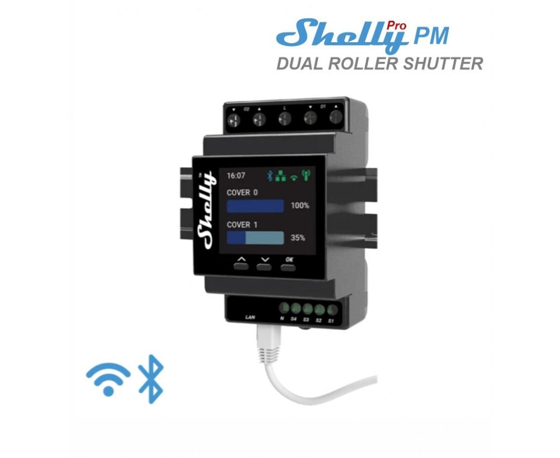
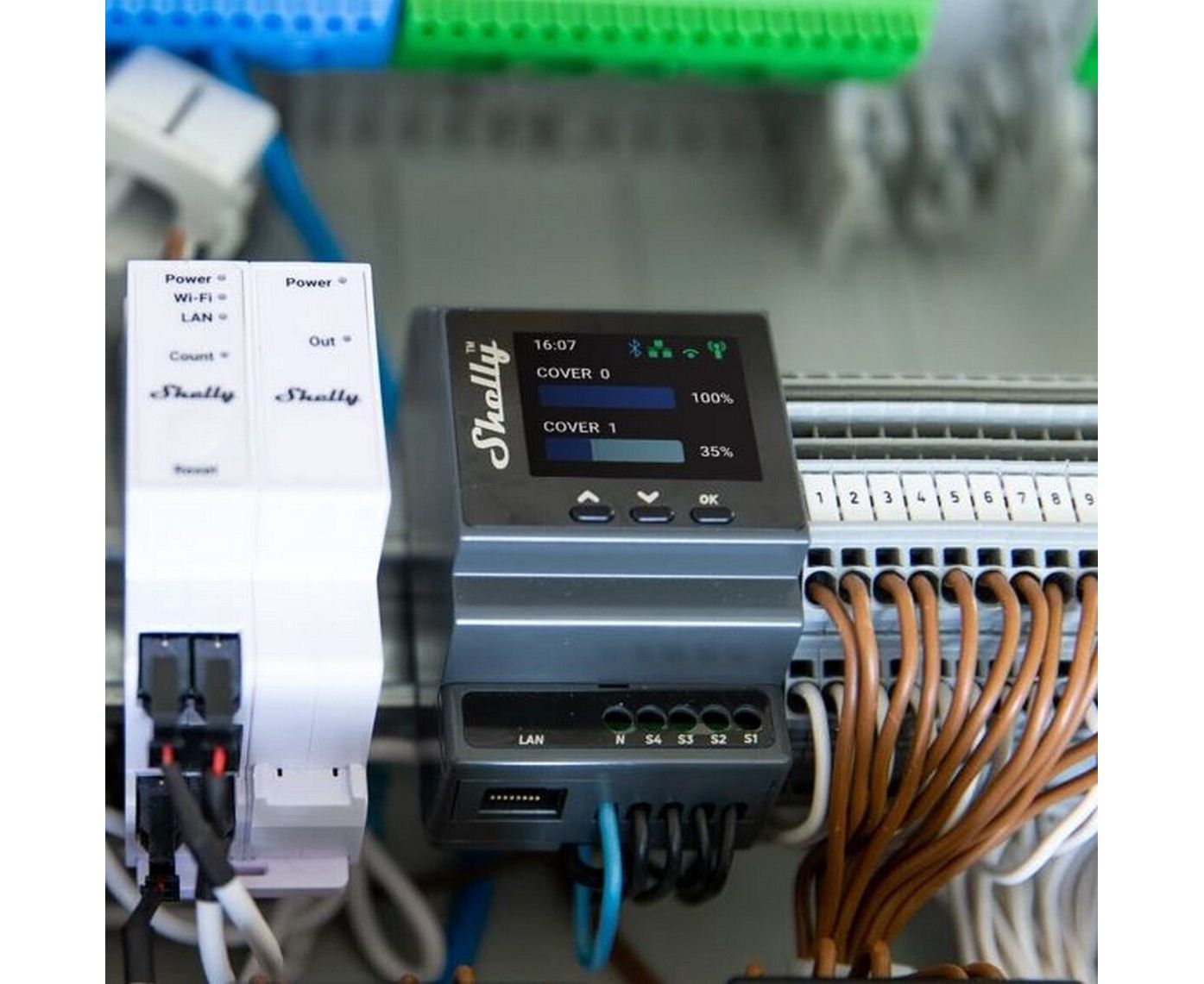
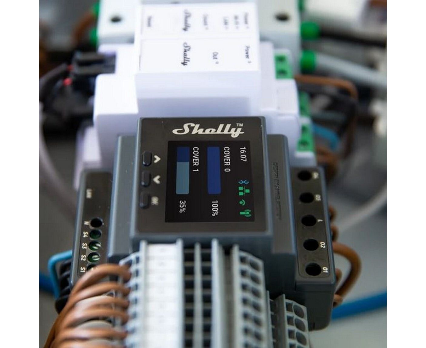
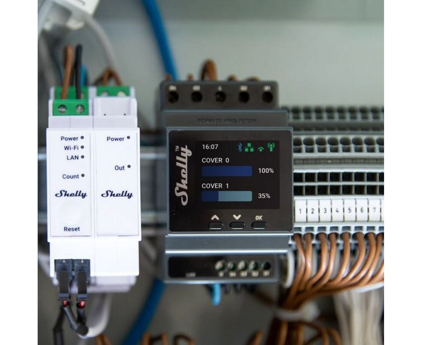
Shelly Pro Dual Cover/Shutter PM (the Device) is a DIN rail mountable smart dual cover controller with power measurement capabilities. Enhanced with all the gen2 firmware flexibility and LAN connectivity, it provides professional integrators with many more options for end-customer solutions. It can work standalone in a local Wi-Fi network or it can also be operated through cloud home automation services.
Shelly Pro Dual Cover PM can be accessed, controlled, and monitored remotely from any place where the User has internet connectivity, as long as the device is connected to a Wi-Fi router and the Internet.
Shelly Pro Dual Cover PM has an embedded Web Interface which can be used to monitor and control the device, as well as adjust its settings.
Residential
MDU (Multi Dwelling Units - apartments, condominiums, hotels, etc.)
Light commercial (small office buildings, small retail/restaurant/gas station, etc.)
Industrial (factories, power plants, water processing, refineries, etc.)
Government/municipal
University/college
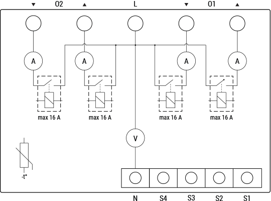
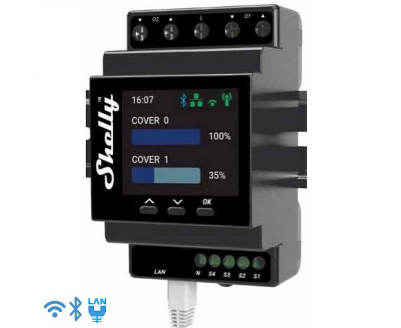
4 switch/button inputs on screw terminals: S1, S2, S3, S4
2 power supply inputs on screw terminals: 1 N and 1 L
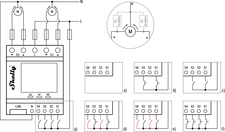
4 relay outputs: ▲ and ▼ of O1, ▲ and ▼ of O2
1 RJ45 connector
⚠CAUTION! Plug in or unplug the LAN cable only when the Device is powered off! The LAN cable connector must not be metallic in the parts touched by the user to plug in or unplug the cable.
Wi-Fi
Ethernet
Bluetooth
Overheating protection
Overvoltage protection
Overcurrent protection
Overpower protection
Bi-directional AC motors with RC Snubbers
Three press buttons on the front plate:
Left button:
Press to scroll up in the currently displayed menu
Middle button:
Press to scroll up in the currently displayed menu
Right button:
Press to wake up the Device display
Press and hold to get into the menu screen
Press to select a menu item
Press and hold while in a sub menu to go back
Color LCD.
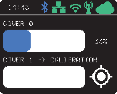
The LCD top bar displays short status information:
Time
Bluetooth connection status
Disabled - no icon
Enabled - blue icon
LAN status:
Disabled - no icon
Enabled, but not connected - red icon
Connected - green icon
Wi-Fi STA status:
Disabled - no icon
Enabled, but not connected - red icon
Connected - green icon
Wi-Fi AP status:
Disabled - no icon
Enabled, but not connected - red icon
Connected - green icon
Cloud status:
Disabled - no icon
Enabled, but not connected - red icon
Connected - green icon
The rest of the LCD is used to display the Device menu screens:
Main (default) screen displays for each cover:
Name of the cover (can be changed in the device settings).
Slider, which visualizes the position of the cover.
Notification area, which shows the position of the covers in percentage or an icon indicating an event (calibration, obstruction, overvoltage, overcurrent, or overpower).
The events are also transcribed next to the cover name.
Network:
Wi-Fi AP enable/disable
Wi-Fi STA enable/disable
Ethernet enable/disable
Bluetooth enable/disable
Status:
Displays complete status information
Maintenance
Wi-Fi reset
Factory reset
Reboot
|
Type |
Value |
|
|---|---|---|
|
Physical |
|
|
|
Size (HxWxD): |
96x53x59 ±0.02 mm / 3.78x2.01x2.32 ±0.02 in |
|
|
Weight: |
150 g / 5.30 oz |
|
|
Mounting: |
DIN rail |
|
|
Screw terminals max torque: |
0.4 Nm / 3.5 lbin (green connectors) |
|
|
Conductor cross section: |
0.5 to 2.5 mm² / 20 to 14 AWG (green connectors) |
|
|
Conductor stripped length: |
6 to 7 mm / 0.24 to 0.28 in (green connectors) |
|
|
Shell material: |
Plastic |
|
|
Color: |
Dark gray |
|
|
Environmental |
|
|
|
Ambient temperature: |
-20 °C to 40 °C / -5 °F to 105 °F |
|
|
Humidity |
30 % to 70 % RH |
|
|
Max. altitude |
2000 m / 6562 ft |
|
|
Electrical |
|
|
|
Power supply voltage AC: |
110 - 240 V |
|
|
Power supply voltage DC: |
N/A |
|
|
Power consumption: |
< 3 W |
|
|
Neutral not needed: |
No |
|
|
Output circuits ratings |
|
|
|
Max switching voltage AC: |
240 V |
|
|
Max switching voltage DC: |
N/A |
|
|
Max switching current AC: |
16 A per output |
|
|
Max switching current DC: |
N/A |
|
|
Sensors, meters |
|
|
|
Voltmeter (AC) |
Yes |
|
|
Ammeter (AC) |
Yes |
|
|
Internal temperature sensor: |
Yes |
|
|
Radio |
|
|
|
RF band: |
2400 - 2495 MHz |
|
|
Max. RF power: |
<20 dBm |
|
|
Wi-Fi protocol: |
802.11 b/g/n |
|
|
Wi-Fi Range: |
Up to 30 m / 100 ft indoors and 50 m / 160 ft outdoors |
|
|
Bluetooth Protocol: |
4.2 |
|
|
Bluetooth Range: |
Up to 10 m / 33 ft indoors and 30 m / 100 ft outdoors |
|
|
MCU |
|
|
|
CPU: |
ESP32-D0WDQ6 |
|
|
Flash: |
8 MB |
|
|
Firmware capabilities |
|
|
|
Schedules: |
20 |
|
|
Webhooks (URL actions): |
20 with 5 URLs per hook |
|
|
Scripting: |
Yes |
|
|
MQTT: |
Yes |
|
|
CoAP: |
No |
|
|
Terminals |
|
Wires |
|
|---|---|---|---|
|
O1, O2 |
Cover 1 and Cover 2 output terminal pairs |
L |
Live (110-240 V) wire |
|
▲, ▼ |
Cover direction output terminals |
N |
Neutral wire |
|
S1, S2 |
Switch/button input terminals for controlling Cover 1 |
|
|
|
S3, S4 |
Switch/button input terminals for controlling Cover 2 |
|
|
|
L |
Live (110-240 V) terminal |
|
|
|
N |
Neutral terminal |
|
|
|
LAN |
Local Area Network RJ 45 connector |
Για την καλύτερη απόδοση και σωστή λειτουργία όλων των συσκευών πρέπει σε κάθε εγκατάσταση να χρησιμοποιούνται τα εγκεκριμένα υλικά
© 2004 - 2025 e-Wireless.gr. Production by interTEN
Η ιστοσελίδα χρησιμοποιεί cookies για την ευκολία της περιήγησης, την εξατομίκευση περιεχομένου και διαφημίσεων και την ανάλυση της επισκεψιμότητάς μας. Δείτε τους ανανεωμένους όρους χρήσης για την προστασία δεδομένων και τα cookies.
Τα παρακάτω cookies μας βοηθούν να βελτιώνουμε την εμπειρία χρήσης σας.